High
Power Wire Wound Resistors application
notes
A. Choosing Power Wire Wound
Resistors and parameters determination :
1.
Resistor power is
calculated by W=I2R
where :
W = resistor power I = maximum loading current
R = resistor rated resistance or
the maximum rheostat
resistance value
2. Never overload a power resistor
beyond the specified voltage, rated
power and current.
3. We recommend choosing a resistor
with a rated power of at least 1.3 to
4 times higher than the actual loading power if your
application requires the resistor to run continuously at full Power.
Extra safe margin power/current can extend the resistor’s service
life and lower its surface temperature.
4. If the maximum or surge power
is larger
than the rated resistor power,
please tell the actual working condition like peak/surge voltage,
resistance value, duty cycle, loading duration, repetition rate
and any cooling system around.
5. If the surge/peak voltage is larger
than the rated resistor Voltage
= SQR(P*R), please tell us the
peak-to-peak
voltage range, duty
cycle, repetition
rate per unit time or
frequency,
loading duration and any cooling system around.
6. Most of our resistors can withstand 5-10
times the rated power for 5 seconds, depending on the current pulse
width, resistor series, installation and cooling system.
7. There are no standard resistance
values for power resistor. It is better to tell
your application's working
voltage,
loading duration and
duty cycle for the Low Ohmic
Power Resistors. A different voltage can induce a very different
resistor current. Different raw materials and production processes
might need to withstand the higher
current and temperature.
For example, load current for 1 ohm and 5 ohm 10kW
power resistors
are
100A and 44A, respectively.
8. The resistor’s maximum working
voltage must obey Ohm’s Law SQR(P*R)
9. We recommend choosing Low-Inductive
Resistors for frequency
sensitive applications.
10. Most of our Power Resistors can
be manufactured according to customers’ applications like
resistance,
rated power,
resistor size,
mounting fixture and
inductive / low
inductive, pulse
voltage condition, etc.
11. Do not touch the
resistor after
connecting to a power source due to the
high surface
temperature and the chance of getting
ELECTRIC SHOCK.
12. The salty, dusty and corrosive
environment can affect the power resistors performance.
B. Other
application notes:
1. The
resistor surface temperature can reach as high as 100°C to 500°C while at full
load, depending on resistor
series, power
rating,
resistance value, working conditions, ambient temperature
and cooling system design, etc.
In general, keeping the
resistor surface temperature below
150°C to 250°C, depending on the above
factors, can extend the resistor service life
and stabilize the resistance value.
2.
Adding a cooling system such as external forced cooling fans can
lower resistor surface temperature. Do not cover the resistors!
3. Use guards and warning
labels where necessary for the power
resistors.
4. We recommend keeping all
temperature-sensitive components away from the resistor.
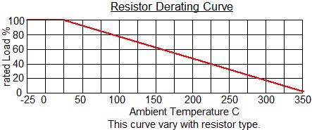
5. Below is one of the Derating Curves
for power resistors in general. Please
contact us for an individual
resistor’s derating curve.
6.
Always clean the resistor
tab terminals before
connection. Do not
clean resistor surface with organic solvents.
7. Do not scratch the resistor surface with
any hard or pointed object.
8. DDR-F and
DQR-F series power
resistors coat
with UL 94V-0 silicone coating. The resistors should be installed
away from any flammable materials.
9. Silicone coated resistors might emit smoke
during initial power loading. It is a normal phenomenon. After
loading at 100% for 1-2 hours, the smoke emission will stop.
10. The ASZ, AHR and HER resistor
external metal enclosure can be a source of interference for most
sensitive circuits. Grounding the resistor metal housing can solve
the concern.
11. All our load banks RB3A, RLB3A, RB, DB, RBA, DSR-WB, DSR3-WB, FVRB,
and RBC series should be Ground connected below connecting
to the
load source.
.
C. Adjustable Wire Wound
Resistors
DSR-F / Rheostats
FVR / Rheostat Boxes
FVRB
and
DSR-WB series application notes :
1.
Rheostat and Adjustable Wire Wound Resistor
are a type of
wire wound resistors.
2.
From a material perspective, the
allowable current depends on Ohm’s Law and the resistance
wire’s current carrying capacity, whenever the lower one.
Loading beyond this current range can damage the rheostat.
3.
The function of a rheostat is to adjust the circuit current
between the maximum current at the minimum resistance and
the minimum current at the rated resistance.
Ci.
Rheostat parameters determination
:
1.
Rheostat rated Power =
(rheostat maximum load Current)2 x rated Resistance
2. The
current of an existing application determines the maximum
load current before the adjustable power resistor or
rheostat is inserted. This consideration is for circuit
current adjustment – a rheostat in series with a fixed
resistor ( the equivalent circuit).
3.
The maximum current for two rheostats with the same rated
power can be very different.
For example, load current for 1 ohm and 5 ohms 10kW
power rheostats
are 100A and 44A,
respectively.
There are no standard resistance values for
power rheostats.
4.
The rheostat minimum
resistance value
can be calculated using the maximum current and voltage.
5.
The rheostat maximum
resistance value
can be calculated using the minimum acceptable current and
the voltage.
6.
The rheostat workable
power needs to decrease as the resistance is
adjusted towards its minimum value.
The workable power at the adjusted resistance is about the
ratio of (adjusted resistance) to (the
rheostat rated
resistance) x ( rated rheostat power) or
i.e. from the material viewpoint : power per
unit resistance
Cii.
Other
rheostat application
notes :
1.
Load current at
any adjusted resistance value
=< rheostat
rated current
Rheostat is a type of wire
wound resistor, in which the resistance wire can act
similarly to a current fuse. If the loading current exceeds
the rheostat's rated current, regardless of the load power,
the resistance wire will be burn out.
2.
Load power at
any adjusted resistance value =<
rheostat
rated power
3.
Rated
resistance value is not the same as an adjusted resistance
value.
4. The
voltage across a rheostat might need to decrease to avoid overcurrent
when adjusting the
resistance value towards its minimum value.
5.
A fixed power resistor can be connected in series with the
rheostat to protect it from overcurrent damage.
The
rheostat rated resistance =
rheostat power / (maximum
load current)2
The rheostat power = (maximum load
current)2
x rated resistance.
6.
The main role of Adjustable
Power Wire Wound Resistor DSR-F, Rheostat FVR, Rheostat Box
FVRB and DSR-WB is
to decrease, not increase, the electrical current in the
circuit.
7.
Rheostat is for
"continuous
load current"
adjustment
- nearly "continuous
resistance" range
design.
8.
For some situations, we may suggest RBA series
adjustable load
bank.
The load power / current adjustment by preset steps /
switches / circuit breakers – discrete resistance values.
With different ON/OFF combinations, a different load current
can be achieved.
Ciii.
Other rheostat application
notes :
1.
Resistance adjustment is achieved by sliding the metal
brusher across the metal resistance material.
There is a chance of flashover between two metal parts when
the resistance is being adjusted, especially at high
voltage, current and/or power conditions.
It is better to power OFF the load source across the
rheostat before adjusting the resistance values.
2. Do not
touch the adjustable
resistor / rheostat
after
connecting to the power source due to
high surface
temperature and avoid
ELECTRIC
SHOCK.
3.
We recommend choosing a rheostat with a rated
current of at
least 1.3 times higher than the circuit maximum
current if
any application requires the rheostat to run continuously at
the full power.
An extra safe margin power/current can extend
the rheostat’s service life and lower its surface
temperature.
4.
Due to high power application and rheostat consists of metal
movable parts within the rheostat,
we suggest installing the rheostat on a fixed and level
bench to avoid vibration.
5.
The salty,
dusty, humid, high temperature, vibration
and corrosive environment can affect the
rheostat performance.
6.
Both sections A and B
are
valid for the
rheostats.
Cvi.
Rheostat Bank FVRB /
Adjustable Load Bank DSR-WB
options :
1.
Meter
: Ammeter, Voltmeter, Wattmeter,
Ohm meter and Temperature meter
2. OverCurrent
protection
3.
Thermal
protection
4.
Cooling Fans
system